![]()
CQC
![]()
CQC

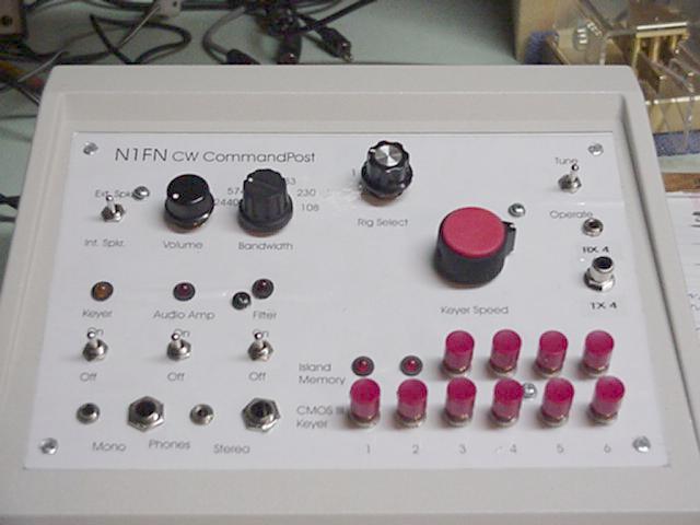
Updated! New panel label, buttons, and some wiring mods... Click here!
(Click here for the related Control Panel article.)
 Click on the pictures to view in full size.
Mission:
Replace four separate accessories-- keyer, keyermemory, audio filter, and audio amplifier-- with one box containing allfour and providing for multiple inputs and outputs.Background:
I use all four of these accessories, all thetime. They were built from kits, and basically occupied three separateenclosures (the audio amplifier was built into the the OHR SCF-1 enclosure. It was a bit untidy, and to add to the confusion on the operating deskI use a variety of rigs, paddles, and headphones, all of which seem torequire an adaptor.The Kits:
CMOS III electronic keyer from Idiom Press, afull featured keyer with 6 memories which can be banked as 18 messages,speed control via pot, and more features than I will ever use..The Result:Island Memory fromJackson Harbor Press adds four additional memories, and the ability torecord message memories "live" while sending.
SCF-1 SCAF Filter from Oak Hills Research (no longer availablebut TechAmerica sells a Vectronicx kit which will do), a switched-capacitanceaudio filter optimized for CW..
A one-watt audio amplifier from Radio Shack (nolonger available but one-watt amps are common).
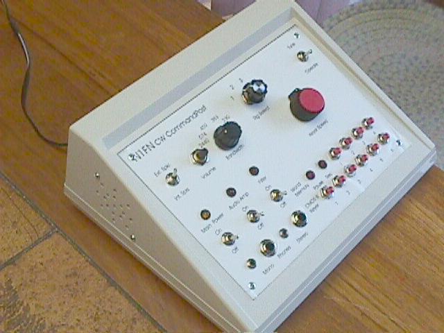
The box is a 10" wide "keyboard box" available from severalsources. Note that while the box itself is plastic, the front paneland rear panel are removable aluminum plates.
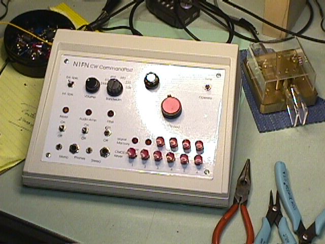
In addition to the features of the individualkits described above, the CommandPost has the following features--General Comments:Power supply: everything is powered from a single12V (nominal) connection.
Device Selection: switches provide for turning theSCAF filter and the audio amp on (or bypassing them) individually, withLED indicators.
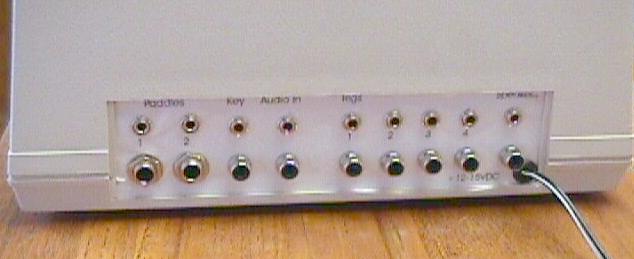
Keyer I/O options: the CommandPost has a front panelrotary switch which is used to select one of FOUR rigs, which can be connectedsimultaneously on the back panel by either RCA phono jacks or 1/8" phonejacks. Four paddles and two straight keys can be connected (the twomarked inputs for paddles offer parallel 1/4" and 1/8" stereo jacks, thekey input offers RCA phono and 1/8" jacks). There is also a"tune" switch to key the selected rig, mounted at the upper right cornerof the front panel.
Audio I/O options: Audio input is via either RCAor 1/8 phone jack. Output is to either stereo or mono 1/4" and 1/8"jacks on the front panel, or a speaker (internal or external, switchedon the front panel). There is a volume control for the audio amp. The stereo headphone jacks are provided for simple connection of stereoheadphones (tip and ring are connected on the jack), but will provide for"true" stereo output if and when I get around to playing with some "spatialeffect" ideas.
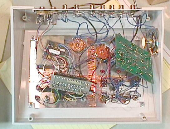
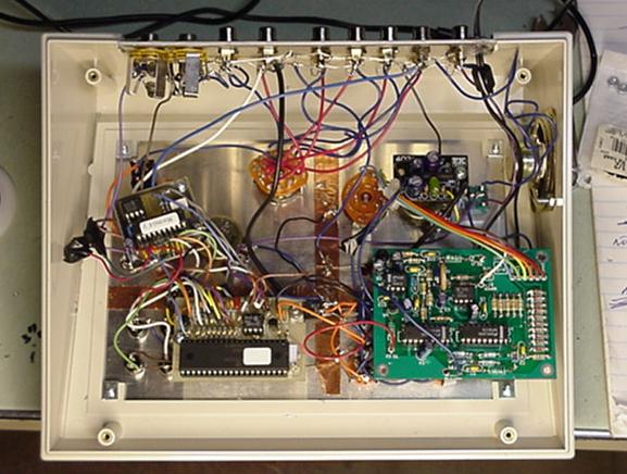
I haven't shown the inside of the CommandPostbecause, frankly, it's a nightmare of point to point wiring and unsupportedcircuit boards. There was an intention to screw each of the boards ontothe base of the box (posts are provided) but I found I couldn't get atthem when the time came to put the panels with attached electronics intothe box. In fact, on the inside at least, this could be the absoluteugliest construction job I've ever done!The panel labelling was done with Corel Draw 8. I did the drilling templates first, using X's to mark hole positions. Including the speaker "grill" on the side of the box, there were 64 holesof various sizes. Then I added the control and jack labels, deletedthe X's, and printed the resulting panel label on 8.5x11" white label stock. I applied the label to the drilled panel, covered it with transparent vinyladhesive book cover material, and cut out the holes from the backusing a hobby knife. I've used this method of labelling before,but do to the amount of handling the panels got after the labels were appliedthere were some problems with dirt and such so I regard the result as onlymarginally acceptible.
There were some logistical problems regarding the audiooutput-- I found I had to choose beteween having all the "other" headphonesjacks, and the external speaker disconnect as soon as one headphone plugis inserted, or leave all the headphone jacks "live" regardless of speakerselection or actual use. I chose the latter course as it could behandy to plug in two sets of headphones. Did I say some logisticalproblems?
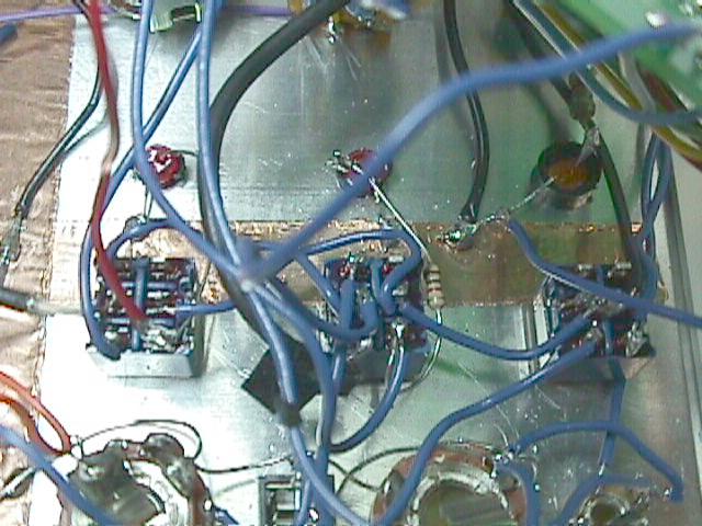
The inside of the the CommandPost is truly ugly-- I hadsome qualms about even showing you, but what the heck. The close-upview on the right is the three DPDT switches that control power to thekeyer, filter, and amp, and switch the audio through the filter and amp.Now that I see the pictures, I should explain the copper strips that arevisibile. It's copper tape, with conductive adhesive. It providesa good ground bus that is much easier to solder to than the aluminum panel.
Click on the pictures to view in full size.I have some "interference" concerns in that the CMOS IIIkeyer is an RF generator, and there is so much wire in the audio sectionsthat there could be some problems. I haven't used the CommandPostenough yet to know whether I will have to go back and do some shielding,and/or by-passing.
 Clickto view in full size
I wasn't particularly happy with the small buttons I had used, and replacing them turned into a major project, including the following modfications"
Click to view in full size
I found it was still a hassle plugging things into theback, especially since I usually wanted to use the CP for audio processingas well as keying. The existing key line (rig) switch had an unused position, so I re-wired the smaller (1.8" phone) jacks to use for fourseparate audio inputs.
That wasn't a complete fix, because I am often testing a rig which I don't want to hook up permanently, so I put parallel keyline and audio input jacks (parallel with "rig 4") on the front of the panel.
While I was at it I also tidied up the the wiring a bit and mounted each of the four circuit boards on standoffs. The screws for the standoffs are on the front panel, which is not as pretty as itmight be, but it was an effective solution.
 Return to CQC Library Page
Return to N1FN's Control Panel article
Return to CQC Home Page
About |
Contact |
Home |
Join |
Meetings
&
Events |
Members |
Merchandise |
Newsletter |
Site
Index |
Copyright
© 1994 -